On the maximum bandwidth attainable by power factor correctors with a standard compensator
Fecha de publicación:
Versión del editor:
Citación:
Descripción física:
Resumen:
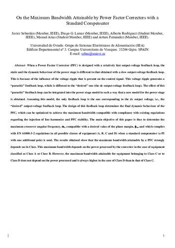
When a power factor corrector (PFC) is designed with a relatively fast output-voltage feedback loop, the static and dynamic behaviors of the power stage are different from those obtained with a slow output-voltage feedback loop. This is because of the influence of the voltage ripple that is present on the control signal. This voltage ripple generates a “parasitic” feedback loop, which is different from the “desired” one (the dc output-voltage feedback loop). The effect of this “parasitic” feedback loop can be integrated into the power stage model in such a way that a new model for the power stage is obtained. Assuming this model, the only feedback loop is the one corresponding to the dc output voltage, i.e., the “desired” output-voltage feedback loop. The design of this feedback loop determines the final dynamic behavior of the PFC, which can be optimized to achieve the maximum bandwidth compatible with compliance with existing regulations regarding the injection of line harmonics and PFC stability. The main objective of this paper is, thus, to determine the maximum crossover angular frequency ω0 compatible with a desired value of the phase margin φm and that complies with EN 61000-3-2 regulations in all possible classes of equipment (A, B, C, and D) when a standard compensator (a PI with one additional pole) is used. The results obtained show that the maximum bandwidth attainable by a PFC strongly depends on its class. This maximum bandwidth depends on the power processed by the converter in the case of equipment classified as Class A or Class B. However, the maximum bandwidth attainable for equipment belonging to Class C or to Class D does not depend on the power processed and is always higher in the case of Class D than in that of Class C
When a power factor corrector (PFC) is designed with a relatively fast output-voltage feedback loop, the static and dynamic behaviors of the power stage are different from those obtained with a slow output-voltage feedback loop. This is because of the influence of the voltage ripple that is present on the control signal. This voltage ripple generates a “parasitic” feedback loop, which is different from the “desired” one (the dc output-voltage feedback loop). The effect of this “parasitic” feedback loop can be integrated into the power stage model in such a way that a new model for the power stage is obtained. Assuming this model, the only feedback loop is the one corresponding to the dc output voltage, i.e., the “desired” output-voltage feedback loop. The design of this feedback loop determines the final dynamic behavior of the PFC, which can be optimized to achieve the maximum bandwidth compatible with compliance with existing regulations regarding the injection of line harmonics and PFC stability. The main objective of this paper is, thus, to determine the maximum crossover angular frequency ω0 compatible with a desired value of the phase margin φm and that complies with EN 61000-3-2 regulations in all possible classes of equipment (A, B, C, and D) when a standard compensator (a PI with one additional pole) is used. The results obtained show that the maximum bandwidth attainable by a PFC strongly depends on its class. This maximum bandwidth depends on the power processed by the converter in the case of equipment classified as Class A or Class B. However, the maximum bandwidth attainable for equipment belonging to Class C or to Class D does not depend on the power processed and is always higher in the case of Class D than in that of Class C
ISSN:
Identificador local:
20101297
Patrocinado por:
This work was supported by the Spanish Ministry of Education and Science under Project TEC2007-66917/MIC and Grant AP2008-03380
Colecciones
Ficheros en el ítem


